


BOSON MAKE BOSOFLEX GEAR COUPLINGS
The gear couplings are flexible in nature and accommodate the misalignment of connecting shafts, while compensating both on in built misalignment and installation misalignment for driven and driving equipments. These gear couplings are flexible, because teeth on hubs and teeth inside cover are suspended in nature so that they can compensate the misalignment. In order to avoid vibration, produced by rotating Mass, the gear teeth need to have a proper radial clearance at time of lower speed transmission of torque. As speed of torque gets higher, this Gear Teeth center on their working flank, which provides distribution of load on all teeth that are equal.
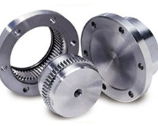
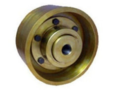
Full Gear coupling
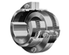 Full Gear coupling is designated as both hubs and sleeves are having outer and inner teeth respectively. Gear coupling Teeth are floating because teeth on outer surface of hub have spherical shape and teeth inside cover have cylindrical shape, have appropriate tangible clearance. The olive shaped tangible teeth, outer spherical gear teeth allow the teeth to float and slide about central axis within range, and this movement of teeth provides flexibility to Gear Couplings. By proper lubrication, conventional stress development is avoided.
Boson always put forward for dynamic balancing as per class and rotating mass and specifications of AGMA 9000 – C90 in case of HIGH RPM as main equipment has the chance for mass imbalance to support sensitive. A Half Rigid Gear Coupling can hold Axial and Angular Misalignment. In case of Full Gear Coupling, it can accommodate Parallel Angular and Axial Misalignment also. It is also to be remembered combined, axial and parallel misalignment can vary for maximum speed, torque can be transmitted, and models of couplings can be selected based on these factors, in order to avoid early and excessive wear. Proper lubrication and maintenance is required time to time.
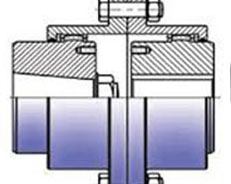
Half Gear Coupling
 Half Gear Coupling comprises one flexible geared half and one rigid half. It does not accommodate parallel displacement of shafts but does accommodate angular misalignment. This type of couplings are primarily used for “floating shaft” applications.
Mill Motor Hubs
 Used frequently in many mill applications, taper bored mill motor hubs allow for rapid mounting and removal without damaging the shaft or bore. Hubs are available to suit standard AISE mill motor frames or can be produced to suit non standard tapers.
Spacer Type Gear Couplings
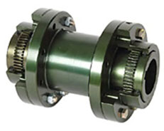 Spacer type gear couplings connect shafts with large distances between shaft ends, with all the high torque performance benefits of a standard gear coupling.
The Brake Drum Type Gear Coupling
 The brake drum type gear coupling is used to connect the motor and gearbox shaft or gearbox and machine shaft.The brake is fitted on the brake drum.Thus it serves dual purpose of being a coupling and brake drum.Brake drum type coupling is mainly used to stop the service equipment without switch off the motor.Basically a mechanical force is applied from outside to stop the equipment.
Normally In this type has three parts : the brake drum,Hub and Sleeve.As a special case it is available in 5 parts also.In that case there will be 2 hubs,2 sleeves and 1 brake drum. This is Robust in design.
Floating Shafts
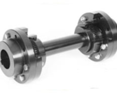 Floating shafts can be used with conventional flexible gear Couplings where the distance between driving and driven shaft is more than 15 Ft.
Why Us ?
Boson Gear Couplings are manufactured with Forged Steel and Heat Treated and Machined. The use of steel for gear couples are Nitrolloy N/ 135, AISI 4140, AISI 1045 and these are tempered and hardened before going to machinery. In some of GEAR Couplings, machine gear teeth are surface hardened by thermo chemical treatment or thermal in order to increase load capacity. For Gear Coupling nitroxidation, gas nitridiing and tempering in induction oven is done. At the last stage anti oxidant and anti corrosive treatment is also done.
Normally in our Standard Gear Coupling made from AISI 1045, unless otherwise specified, nitroxidation treatment for limiting surface corrosion. Besides this treatment can improve wear resistance, surface hardness and increase service under life under rotational speed and high misalignment. The Gear Coupling is selected and is based on operating data like horse power , Shaft Dia for both Driven and Driving Side, Rotation Per Minute and Type of Equipment.
We recommend to perform a dynamic balancing of the rotating masses- class and requirements to be specified (See AGMA 9000 C90)- in case of the high rotation speed or when the equipments having supports sensitive to the mass imbalance are involved. A single engagement of the gear teeth (half-coupling) can compensate both angular and axial misalignments, two engagements of the gear teeth (complete coupling) are required to compensate also the parallel misalignments.
Please remember that angular, parallel, combined and axial alignments, maximum speed rotation and transmitted torques must be in accordance with the requirements of every kind of coupling, to avoid excessive or early wear. Maintenance and lubrication have to be careful and precise.
The Gear couplings are properly packaged as per their dimensions, weight, required type of transport and storage. For prevention of oxidation, the interface surfaces or the surface which have been submitted to assembly the operations are protected by a wax film of TECTYL 506 EH. The raw or semifinished wide surfaces of spacer tubes are painted, after sandblasting, by one primer acrylic coat and two final epozy coats, this kind of painting can resist temperatures up to 100-120° C
Infact, we allow several kind of coating as per customer requirements. The torque a gear coupling to the total misalignment between the shafts when connected. The gear couplings must be selected as per the operational data (speed and load), the nominal and max load capacities, the application, the static, and dynamic misalignmenets and the max admitted bore.
- Torsionally Flexible
- Suitable for High Torque Transmission.
- Excellent for shock load
- ExtraLong Life
- Durable
|
|
|
|
|
|
|


